This keyboard had been dropping its Bluetooth link for weeks, with four cells in its battery bay reporting 85% charge the whole time. I took all four out, dropped two fresh cells into the four-slot bay, and left the other two slots empty. The dropouts stopped — and the reported charge went up, to 100%.
Both halves of that are worth explaining. Half the cells should not be enough to run the device at all, and fewer cells should not read higher than more. Neither is a firmware bug. The voltage constraint of a parallel connection, together with cell internal resistance, fixes both outcomes — and bounds what that percentage can express in the first place. What follows is the mechanism, the equations, and the measurements that pin it down.
01 · What was observed
To pin down what the reading actually tracks, the old cells were measured back in, one configuration at a time — the same set of cells throughout, changing only how many were present. Each configuration was confirmed to be a fresh sample by an independent disconnect/reconnect cycle, then sampled continuously for more than 30 seconds to confirm it had settled.
| Configuration | Cells present | Reading | Notes |
|---|---|---|---|
| Old cell A (alone) | 1 | 45% | 8 samples, no jitter |
| Old cell B (alone) | 1 | 45% | 8 samples, no jitter |
| Old cell C (alone) | 1 | 45% | 8 samples, no jitter |
| Old cell D (alone) | 1 | 40% | one quantisation step lower |
| A + B | 2 | 65% | — |
| Old cells ×3 | 3 | 85% | after contacts were reseated |
| Old cells ×4 | 4 | 85% | matches the historical mode |
| New cells ×2 | 2 | 100% | 18 samples, no jitter |
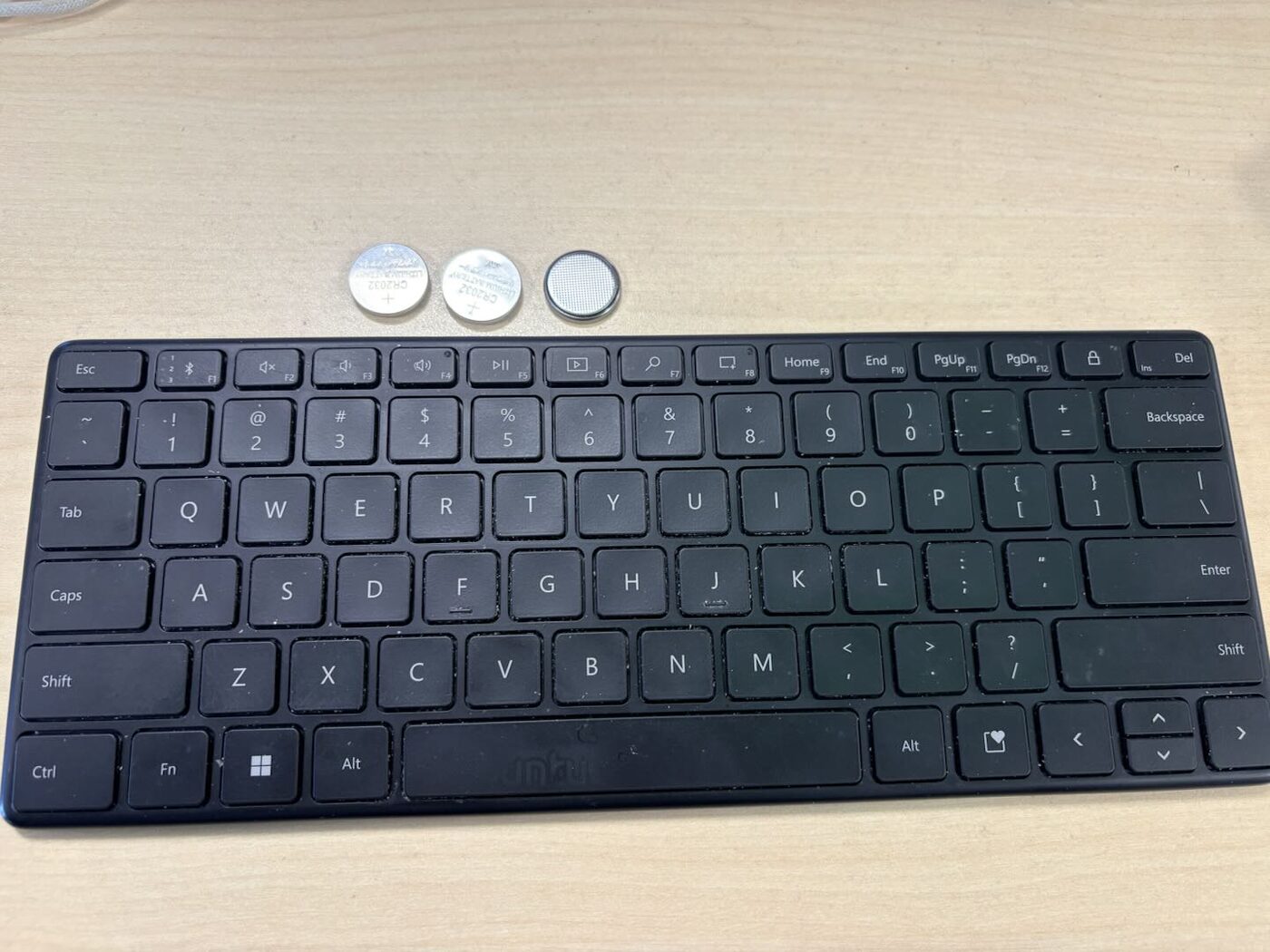
Two results run against intuition: four old cells (85%) read lower than two new cells (100%), and three old cells read exactly the same as four. Cell count neither determines the reading monotonically nor is irrelevant to it. Explaining that shape takes three things — the parallel voltage constraint, cell internal resistance, and the mapping from voltage to percentage.
02 · Parallel locks every cell to one voltage
The four slots are oriented the same way and share a single metal strip, which makes this a parallel connection. The manufacturer documentation agrees: Microsoft’s support page for this keyboard states that it “uses four coin-cell (C2032) batteries” and instructs the user to “make sure the positive end is facing up” — one orientation for all four slots, with no alternation (Microsoft Support). The regulatory filing settles it mechanically: internal photographs submitted for FCC ID C3K1954 show four identical contact assemblies in pure translation — the same side-spring-and-flat-pad arrangement, the same orientation, carried on one continuous strip (FCC filing). Series wiring requires alternating polarity between adjacent slots, which would force a mirrored contact layout. There is none. The defining constraint of a parallel connection is that every branch sits at the same terminal voltage:
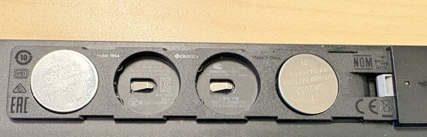
⊕ CR2032 × — the ⊕ means positive side up, printed once for the whole row, so all four slots share an orientation. A series pack requires alternating polarity between adjacent slots, so this alone identifies the connection as parallel. Shown here is the final configuration of this write-up: new cells in slots 1 and 4, slots 2 and 3 empty, with the negative contacts visible at the bottom of the empty slots. The keyboard works in this state, which is a second piece of evidence independent of the marking.Measured result for this deviceWith two cells installed and two slots empty, the keyboard’s Connected property remained true and battery reporting worked normally. A series pack missing a cell is necessarily an open circuit, so this observation alone settles the topology as parallel.
03 · A real cell is an ideal source plus internal resistance
The constraint above explains why the keyboard still runs with cells missing, but not why the reading changes. That requires dropping the “battery as ideal voltage source” simplification and introducing internal resistance — the equivalent series resistance (ESR).
A real cell is equivalent to an ideal voltage source Voc (open-circuit voltage) in series with a resistance Rint. When current flows, part of the voltage is dropped across that resistance, so the terminal voltage measurable from outside is lower than Voc:
- Voc
- open-circuit voltage, set by the chemistry and the remaining state of charge
- Rint
- equivalent series resistance, which rises sharply as the cell depletes
- I
- load current
The decisive property is that Rint rises sharply with depletion — nowhere near a linear decay. Texas Instruments measured this directly on CR2032 cells under pulsed Bluetooth Low Energy loads: internal resistance climbs from roughly 5 Ω on a fresh cell to about 50 Ω by the time ~130 mAh has been drawn, and their design guidance budgets for 1 kΩ at end of life — two orders of magnitude (TI SWRA349). Their conclusion is blunt: “Since the IR increases rapidly as capacity is used, the circuit must be able to manage a very high IR to achieve good effective battery capacity.” This is why an old cell whose open-circuit voltage still looks acceptable collapses the moment it is loaded.
04 · Terminal voltage rises with n toward an asymptote
Combining the two steps, the terminal voltage of n cells in parallel under load current I is:
Vterm(n) = Voc − I · Rint / n
In the voltage domain this gives a monotonic rise with shrinking increments, approaching Voc. What the reported percentage does with that shape depends on f, and the two do not match: the readings saturate earlier than the voltage model predicts. §08 takes that up.
05 · The percentage is a function of voltage, and it cannot see n
The keyboard firmware has a single voltage sampling path. It maps the sampled terminal voltage through a fitted curve to a percentage, then reports a uint8 over the Bluetooth Low Energy (BLE) Battery Service (service 0x180F, characteristic 0x2A19). The specification defines that value as 0 to 100 with 1% resolution (Bluetooth BAS v1.1); every value this keyboard reports is a multiple of 5. The coarser quantisation is the firmware’s own, not a constraint of the transport.
where f is monotonically increasing
Three consequences follow directly, all consistent with the measurements:
- Cell count is invisible. Two new cells and four new cells read the same, because a parallel connection does not change voltage. Cell count changes only capacity (amp-hours add linearly) and equivalent internal resistance. The firmware makes this stronger than it has to be: across four days of logged reports, 95% never appears and 100% appears only with fresh cells — above some threshold the output is clamped, so everything in that region reads identically no matter how many cells produce it.
- Capacity is not measured. This is a voltage proxy, not a coulomb counter (a dedicated circuit that integrates current to track remaining charge). Coin-cell devices do not carry one.
- The reading is optimistic. The lithium-manganese-dioxide discharge curve is flat through its middle section: most of the usable energy leaves while the voltage barely moves. By the time the percentage starts falling, the remaining energy is far below the displayed value.
06 · Masking: single-cell state is not measurable in parallel
The parallel constraint has a further consequence, more significant than the offset in the reading: a spent cell whose internal resistance is high enough that it can barely source current is held at the same rail voltage by the good cells beside it. In the reading it is indistinguishable from a good cell.
The masked cell also keeps drawing current from the good ones. Its magnitude is set by the voltage difference and the sum of the internal resistances:
The right procedure for a parallel bayDo not replace cells one at a time. A weak cell is masked by the good ones, so there is no usable causal signal between swapping any particular cell and the fault disappearing — and throughout the mixed period the new cell is charging the old one. The correct procedure is to remove every depleted cell at once. In a parallel bay a missing cell costs capacity only and does not affect operating voltage, so an empty slot is preferable to an old cell left in it.
07 · How internal resistance causes Bluetooth dropouts
Everything above is steady state. What actually drops the link is the transient: peak current Ipeak during an RF transmit burst is far above the standby current, and the instantaneous drop across the internal resistance scales with it. If the terminal voltage falls below the chip’s brownout reset threshold Vbo, the keyboard loses power and restarts, taking the Bluetooth link down with it.
The logged reports show both the droop and the recovery directly. Readings collapse and return within a single two-minute sampling interval:
17 Aug  14:30   35%  →  14:32   75%
17 Aug  19:16   50%  →  19:18   85%
18 Aug  10:23   60%  →  10:25   85%
20 Aug  17:48   55%  →  17:50   70%
The swing also widens over time. On 17–18 August the readings sit between 85% and 90%; by 20 August the same cells under the same use swing between 55% and 85%. Those cells did not lose thirty points of charge in three days — Rint rose, so identical transmit bursts produced deeper droops. Nothing was inserted or removed during this window (the swapping described in §08 began only on 21 August), so the widening cannot be attributed to contact disturbance. It is visible without any additional instrumentation.
08 · Where the model stops
The model accounts for most of the observations, but two points have to be stated plainly, or this write-up would read as more certain than the evidence supports.
The 1/n rate form does not hold
The saturation value of 85% is solid, and it rests on observation rather than on the model. It is where n=3 and n=4 settle in the controlled test; it is the most frequent value across four days of ordinary use (48 of the 150 reports below); and it is the mode of the longer log kept before the cells were replaced (85%, 62 samples). The first two come from the same capture and are not independent of one another, but the third is a separate record — and none of the three needs a model.
The rate is a different matter. 1/n puts n=3 at 71.7% and n=4 at 75%, while both measure 85% — the readings reach the saturation value faster than 1/n and then stop. The fitted A = 85% does coincide with the observed saturation, but that agreement cannot be read backwards as support for the model, because the fit’s other term is what fails.
The mapping f is why. This write-up treats it as linear, and it is not. Four days of HCI capture recorded 150 battery reports from this keyboard; their distribution shows what the firmware actually does:
reading   25  30  35  40  45  50  55  60  65  70  75  80  85  90  95  100
count      1   1   1   2   3   2   1  17  11  21  11  16  48   9   0    6
All 150 values are multiples of 5, and every step from 25% to 90% is occupied — a fine-grained mapping quantised to 5% at the output, not a handful of coarse levels. Above the top step it clamps, which is why 95% never appears while 100% does. A straight line fitted in percentage space cannot be extrapolated across a range shaped like that, and extrapolating it is precisely what the n=3 and n=4 predictions did.
This locates the failure in f, not in the circuit. Reff = Rint/n follows from the parallel resistance formula and is not in doubt — but it is not tested here either, because these measurements recorded only percentages. Separating the two layers requires measuring Vterm directly, which was not done. Nor is there an account of why a straight line through 45% and 65% should extrapolate to the right intercept while getting the shape wrong; that coincidence is recorded, not explained.
Contact reliability is an uncontrolled variable
One contact failure was observed directly during the session: removing a cell disturbed the shared metal strip and triggered 8 disconnect/reconnect cycles within 50 seconds, with the reading collapsing to 40% — roughly the single-cell level — until the mechanical state settled. This means any insertion or removal can leave a cell not actually connected, and the magnitude of that effect (20 to 45 percentage points) exceeds the effect being measured.
Because of this, an earlier record of “3 cells = 65%” contradicts the later “3 cells = 85%”. The earlier figure is more plausibly a case of one cell not making contact, effectively n=2. But that is a post-hoc hypothesis — observing the expected value first, then invoking a bad contact to explain the deviation. That form of reasoning can explain away any inconvenient data point and has to be labelled as such. Its only independent support is that contact failure is a directly observed failure mode on this device, not a mechanism invented to rescue the data. Even so, it falls short of confirmation.
Reliable conclusions are limited to these three
One. The parallel masking effect is real and large: for the same set of cells, one alone reads 45% while several together read 85% — a 40-point gap. This conclusion is unaffected by the contact problem, because with a single cell present it either conducts or it does not; there is no partially-connected middle state.
Two. This set of cells has high internal resistance. Readings with several cells in parallel are markedly higher than with one, which can only come from a reduced voltage drop. Historical logs reading 85% idle and 70% under load corroborate this independently.
Three. This set of cells is genuinely depleted. Lightly loaded and with enough cells in parallel that the drop no longer moves the reading, they settle at 85%, while two new cells read 100%. Those 15 points are a real difference in state of charge, and neither figure depends on the model.
09 · What carries over
- Do not service a parallel bay one cell at a time. Weak cells are masked, so no diagnostic signal is available, and during the mixed period the new cell reverse-charges the old one, with a leakage risk. Remove all the old cells together.
- A parallel bay may be run under-filled. Missing cells cost capacity and internal-resistance headroom, not operating voltage. Two new cells beat two new plus two old.
- Do not read this percentage as a fuel gauge. It is a voltage proxy: blind to cell count, blind to capacity, and heavily optimistic across the flat section of the discharge curve.
- Record time since last load when measuring. High-internal-resistance cells recover slowly once unloaded, so the same configuration gives different readings at different moments.
References
- Microsoft Support — Use Microsoft Designer Compact Keyboard. Confirms four coin cells and a single orientation for all four slots (“make sure the positive end is facing up”), which is what identifies the bay as parallel. support.microsoft.com
- Texas Instruments, White Paper SWRA349 — Coin cells and peak current draw (Mathias Jensen). Measured internal resistance of CR2032 cells against used capacity under pulsed BLE loads; gives the IR limits at which 15 mA and 30 mA peak draws stop being sustainable. Underpins §03 and §07. ti.com
- Energizer CR2032 Product Datasheet. Nominal 3.0 V, typical capacity 235 mAh to a 2.0 V cutoff, and the 1 µA maximum reverse-charge rating cited in §06. data.energizer.com
- FCC filing, ID C3K1954 (Microsoft model 1954; test report RFBBXY-WTW-P20060146, Bureau Veritas). Internal photographs show the four battery contact assemblies and the main board; the RF section reports a peak output of 0.74 mW (−1.32 dBm) at 2402 MHz. fccid.io
- Bluetooth SIG, Battery Service (BAS) v1.1. Defines Battery Level (0x2A19) as a uint8 from 0 to 100 at 1% resolution, establishing that the 5% steps observed here originate in the keyboard firmware. bluetooth.com